May 2026
3D Printed Cycloidal Actuator
A low-cost, mostly 3D printed cycloidal actuator built around a generated cycloidal profile — an 11:1 single-stage drive that hit ~85% efficiency on the torque bench.
On this page
Actuators are the heart of modern robotics and automation, but their high entry cost makes them hard for an individual to experiment with. I have lofty dreams of building my own intricate robotics systems, and an expensive, hard-to-iterate actuator is exactly the kind of bottleneck that kills a project before it starts. So I set out to design my own.
My goal was a cost-effective, modular architecture I could iterate on quickly. To get there, I prioritized making the actuator mostly 3D printed — it's both very fast and very cheap, which is exactly what rapid iteration needs.
Modularity was a deliberate design driver, not just a buzzword. While this first iteration was built around a generic 5010 BLDC motor, I purposefully designed the CAD so the same architecture can adapt to a wide variety of BLDC motors — swap the motor-mounting interface and the rest of the actuator carries over.
- Reduction
- 11:1
- Output torque
- 1.85 N·m
- Drive efficiency
- ~85%
- Motor
- 5010 BLDC
Why a cycloidal drive
I chose a cycloidal-style drive because, alongside harmonic drives, it offers minimal backlash at high torque density while remaining backdrivable — all properties I want in a robotics actuator. The deciding factor was manufacturability: a cycloidal disk is a far easier printing challenge than the thin, flexible flexspline of a harmonic drive.
To make the design itself iterable, I leaned on the custom Onshape FeatureScript I wrote in an earlier project to generate arbitrary cycloidal profiles. With it I could rapidly tune the cycloidal profile, the gear ratio, and the tolerancing for 3D printing without redrawing geometry by hand each time.
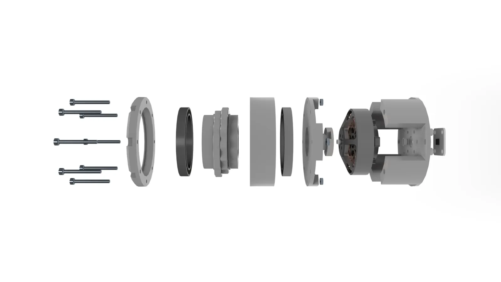
The motion system
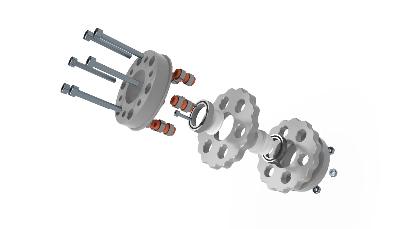
The eccentric input shaft carries two cycloidal disks, offset by 180° from each other. Running a pair out of phase cancels the eccentric mass — eliminating the vibration a single disk would produce — and smooths torque transmission. The upper and lower carriers guide the output motion and mount the interior bearing stacks that the cycloidal disks ride on.
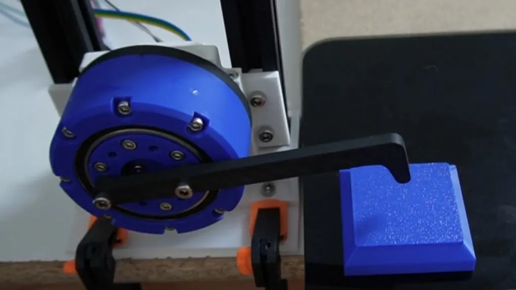
Torque testing
I ran torque tests on an actuator built with a generic 5010 BLDC motor (360 KV) from Amazon. In both tests the system was driven by a B-G431B ESC with an AS5600 encoder running SimpleFOC — I sampled parameters each run and capped current at 3 A. Torque was measured with a lever arm and scale, then computed as force × lever length.
Motor alone:
| Trial | Force (g) | Lever (mm) | Current (A) | Torque (N·m) |
|---|---|---|---|---|
| 1 | 203 | 100 | 2.9 | 0.199 |
| 2 | 202 | 100 | 2.9 | 0.198 |
| 3 | 202 | 100 | 2.9 | 0.198 |
| Avg | 202.33 | 100 | 2.90 | 0.198 |
Fully assembled actuator (11:1 ratio):
| Trial | Force (g) | Lever (mm) | Current (A) | Torque (N·m) |
|---|---|---|---|---|
| 1 | 1900 | 100 | 2.9 | 1.864 |
| 2 | 1880 | 100 | 2.9 | 1.844 |
| 3 | 1890 | 100 | 2.9 | 1.854 |
| Avg | 1890.00 | 100 | 2.90 | 1.854 |
At an 11:1 ratio, an ideal drive would multiply the motor's 0.198 N·m up to ~2.18 N·m. The actuator delivered 1.854 N·m, for a measured drive efficiency of 84.9%.
~85% efficiency is a solid result — commercial single-stage cycloidal drives typically land in the 85–95% range.
There's clear room to push it higher: better lubrication, printing in something stiffer than PLA, tightening the part tolerances further, or adding rollers to the outer pin elements would all cut losses and bring it closer to the commercial range.
CAD
Thanks to the modular design, the actuator has versions tailored to different motors. You can explore the full CAD for the version built around the MAD Motors 5010 110KV EEE BLDC in Onshape.