March 2026
Motorized Monitor Stand
A custom dual-monitor stand I designed and machined to motorize my oversized corner desk — Arduino-driven, with homing, jogging, and saved sit/stand positions.
On this page
I have a corner bench I often work at that's impractically large to turn into a full standing desk. I still wanted the benefits of one, though — so the obvious solution was to build a custom, motorized monitor stand. It carries dual monitors and supports homing, jogging, and two saved positions for sitting and standing.
I did the full mechanical design in Onshape (view the CAD here) and machined all of the custom parts myself.
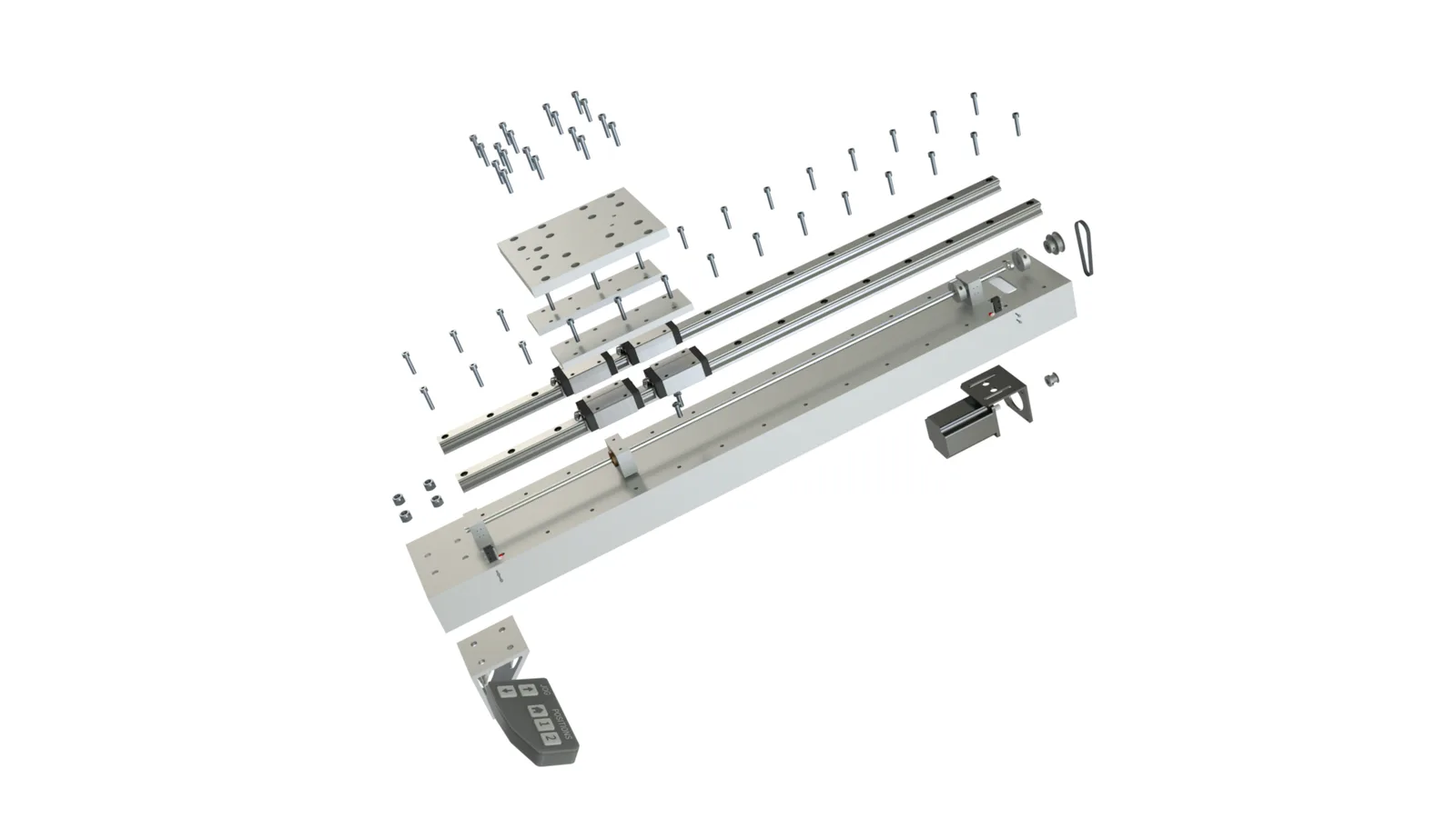
- Travel
- 650 mm
- Payload
- ~40 lb
- Drive
- TR8×2 lead screw
- Motor
- NEMA 23 stepper
Sizing the motor
To pick the motor, I sized the lead-screw drive — working out the torque needed to raise the load and checking that the trapezoidal screw won't back-drive (so the stand holds its position). The total torque splits into the torque to hold and raise the load and the torque to accelerate the system:
This analysis ignores friction outside the lead-screw/nut interaction, and leaves out the motor's internal inertia and the small pulley and belt used to drive the screw.
Load torque
The drive uses a TR8x2 single-start trapezoidal lead screw:
| Parameter | Symbol | Value |
|---|---|---|
| Pitch / lead | 2 mm | |
| Outer diameter | 8 mm | |
| Mean diameter | 7 mm | |
| Half flank angle |
The screw is stainless steel running in a bronze nut, which gives a typical greased friction coefficient of . From the geometry:
The half flank angle inflates the friction into a virtual friction coefficient and angle:
which sets the drive efficiency:
Estimating the two monitors, arms, and carriage at ~40 lb (), the torque to raise the load is:
Will it back-drive?
A screw holds its position (won't back-drive under load) when the lead angle is smaller than the friction angle, . Here , so the stand stays put with the motor unpowered — no brake needed.
Acceleration torque
The rest of the torque accelerates the system, (here is angular acceleration, not the lead angle above). Sizing the motion for the full travel:
| Quantity | Symbol | Value |
|---|---|---|
| Total travel | — | 650 mm |
| Full-travel time | 60 s | |
| Linear speed | ~11 mm/s | |
| Rotational speed | 5.5 rev/s = | |
| Time to full speed | 2 s | |
| Target acceleration |
The inertia is the lead screw's rotational inertia plus the reflected inertia of the linearly moving payload:
That acceleration torque is negligible — roughly 2,300 times smaller than the load torque — and that makes physical sense. The lead screw's 2 mm lead is a huge reduction from rotation to translation, so the payload's mass reflects back to the screw through a factor of order . Eighteen kilograms of monitors ends up "feeling" like less than of rotational inertia, so almost all of the motor's job is simply holding the load against gravity, not accelerating it. The total requirement stays essentially .
The stand is controlled by an Arduino, which takes inputs from a 5-button controller and the limit switches. It's driven by a NEMA 23 stepper motor through a DM556 stepper driver. You can find the code on my GitHub here.